Setup Settings
The Setup Settings step allows users to specify site-specific parameters under predefined categories, such as Design, Signs and Electricty Grids. Users can create entries for the various types they wish to model, providing a clear and structured approach to managing site-related items.
Signs, Electricty Grids and Loader Operating Conditions will appear by defualt. Additional list types may become accessible through the use of plug-ins, allowing for further customization and flexibility.
List items are managed using the toolbar located at the top of the page. More information on the functions within the toolbar can be found in the Common User Controls page.
Design Settings
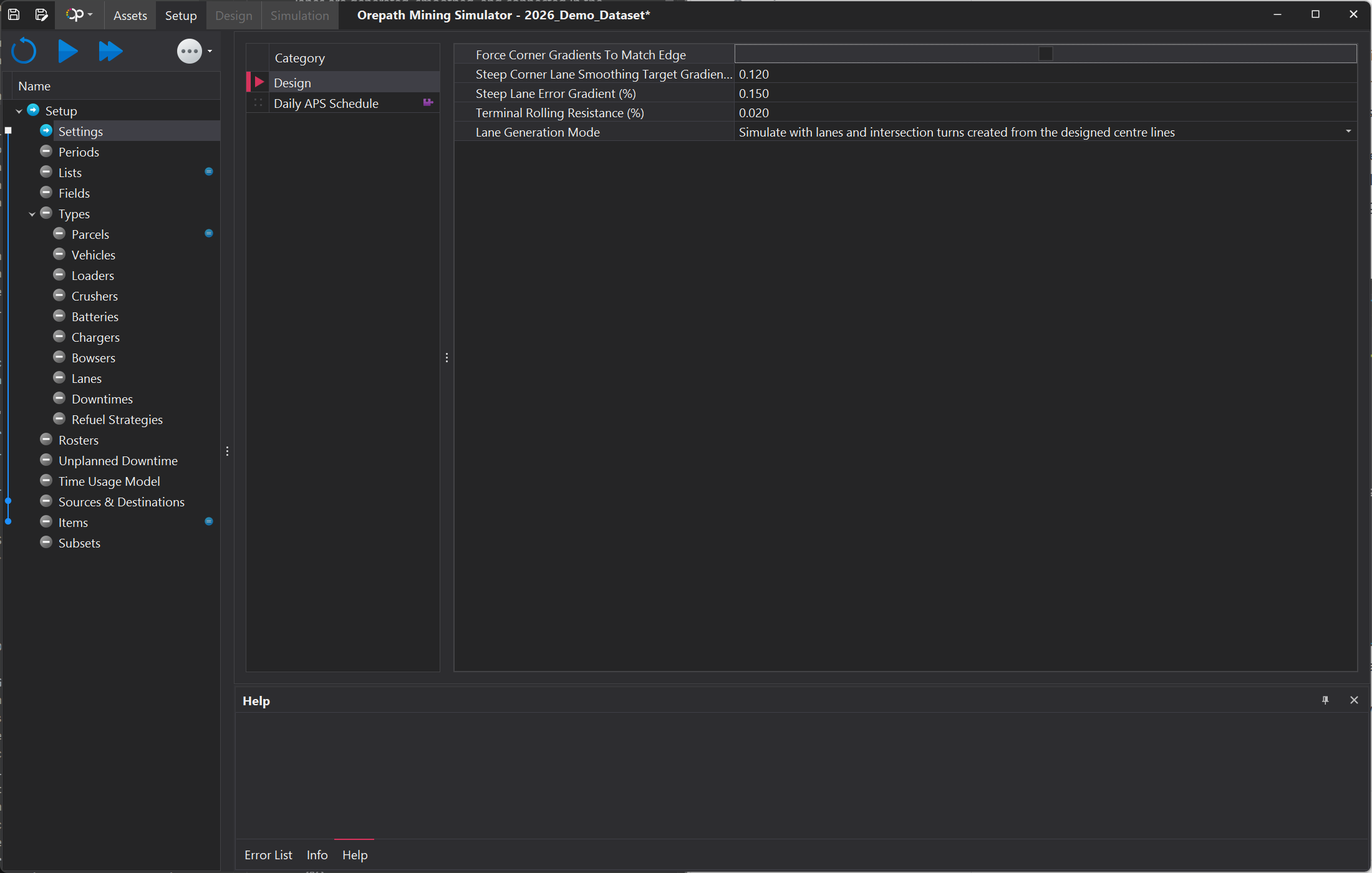
Design settings are used to control how haul road lanes are generated, smoothed, and connected in the simulation. These options help ensure that the lanes follow realistic gradients, have proper corner transitions, and match the intended road design before running the simulation.
Some design settings are controlled using checkboxes or drop-down boxes. A checkbox is used to turn a setting on or off, while a drop-down box allows the user to choose one option from a list. For example, Force Corner Gradients to Match Edge is a checkbox setting. When this option is enabled, the corner lane gradient is forced to match the connected road edge, and the Steep Corner Lane Smoothing Target Gradient setting may be hidden because it is no longer required.
| Menu Selection | Description |
|---|---|
| Force Corner Gradients to Match Edge | A checkbox setting used to make the gradient of corner lanes match the slope of the connected road edge. When enabled, it creates smoother and more consistent lane connections at corners. This may also hide the Steep Corner Lane Smoothing Target Gradient setting because the gradient is controlled automatically. |
| Steep Corner Lane Smoothing Target Gradient | Sets the target gradient used to smooth steep corner lanes. A lower value creates gentler corner transitions, while a higher value allows steeper corner transitions. This option may only appear when Force Corner Gradients to Match Edge is disabled. |
| Steep Lane Error Gradient (%) | Defines the maximum allowed difference or error in lane gradient. If the lane gradient exceeds this tolerance, the system may flag it as an issue. |
| Terminal Rolling Resistance (%) | Sets the rolling resistance value used at terminal or end-point areas. This affects how vehicle movement is calculated in the simulation. |
| Lane Generation Mode | A drop-down setting used to select how lanes are generated from the designed centre lines. The user can choose whether the simulator creates lanes with intersection turns or only follows the designed centre lines. |
Signs
The software utilises variables to manage road speeds that users may want to adjust between simulation runs. This method streamlines the process, enabling users to easily test and analyse various scenarios without the need for manual configuration adjustments each time. By using variables, significant time savings are achieved, and the risk of errors is minimised, leading to smoother and more accurate simulations.
Some examples of variable applications for speed limits within an operation might be:
- On Bench/Lift: Speed limits for roads within a certain proximity to load units or tip heads.
- Main Road Network: Speed limits for the primary haul routes routes.
- Narrow Single Lanes: Speed limits for restricted-width lanes where manoeuvrability may be limited.

Naming Guidelines
Character Count
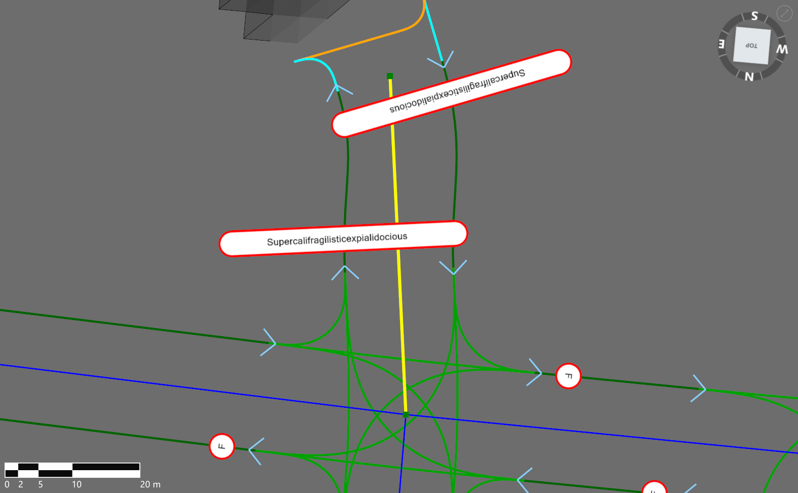
Keep sign names short to ensure they display neatly across different viewports. Longer names can appear cluttered and visually unappealing.
Designation
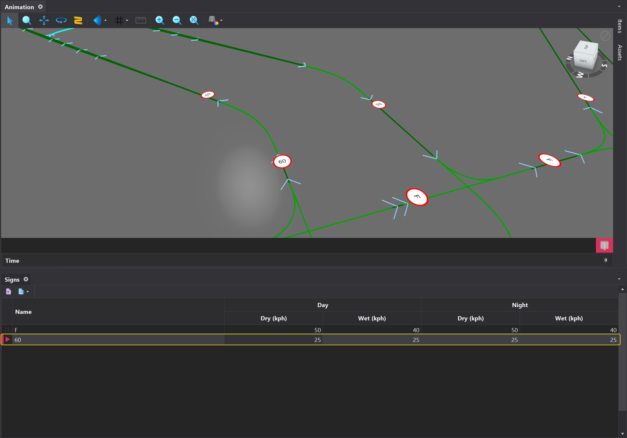
Avoid naming speed limits based on specific speeds, as its possible the actual speed along a segment may differ from what is indicated on the sign.
Electricity Grids
In this list, the on-site electrical grids must be defined. However, the actual capacity of the electrical grid is not specified until the 'Scenarios' tab, allowing for easy testing of different grid capacity scenarios.

Loader Operating Conditions
In the software, it's possible to model different Operating Profiles for loaders, such as hard and soft digging or experienced and inexperienced operators. The first step involves defining these Operating Profiles in the Lists step. Once defined, these profiles will flow through to all load unit models, which are set up in the Loaders step. This means that all load unit models will have 'Soft' and 'Hard' operating conditions, where the appropriate rate can be specified—provided that 'Soft' and 'Hard' conditions have been defined.
